
Research Interests
-
Production of premium fuels and chemicals from gasified biomass
-
Low temperature hydrodeoxygenation
-
Advanced equipment and laboratory design
-
Membrane separations
Production of Premium Fuels and Chemicals from Gasified Biomass
Plant materials contain complex chemical structures (see for instance Dr. Gregg Beckham's discussion of lignin), but through thermal heating in limited O2 (gasification), it can be converted to the simple building blocks of CO and H2, also known as "syngas." The challenge then becomes converting this syngas into something valuable (like fine chemicals) and/or something that can displace our major sources of greenhouse gases (like gasoline, diesel, and jet fuels). And of course, this must be done inexpensively so our bottom line is helped just as much as the environment.
I like to focus on single or dual-step processes that convert syngas to fuel products, and one of my career goals is to find a way to make diesel and jet fuel from biomass at a cost that competes with the market price of oil. Given the costs of producing and delivering biomass to a conversion facility and the energy costs associated with gasification (studied in detail by our Analysis team), we know that any such process must deliver a high yield and the product must be of better quality than petroleum analogues. So this is our target. My group has recently studied the direct conversion of syngas to mixed linear alcohols in partnership with The Dow Chemical Company, and we're currently developing catalysts and processes that convert methanol (made commercially from syngas) to ultra-premium gasoline and jet-range hydrocarbons (schematic below). The results to date are compelling. See our recent patent application and feature publications below for more detail on our current work in this area.

Low-Temperature Hydrodeoxygenation
The catalytic removal of heteroatoms (e.g., covalently-bound sulfur in crude oil hydrocarbons) represents a major cost in oil refining, and catalyst scientists have been studying and improving the process for nearly a century. When biomass goes through a lower-temperature heating process to produce oil instead of a gas (pyrolysis), a diverse mixture of oxygenated products are formed, as shown in this plot from our recent review on bio-oil upgrading:

The oxygen in these products is heteroatomic, and because we want hydrocarbons as a finished product, we must get the oxygen out. Two ways to do this include hydrodeoxygenation and direct deoxygenation:

The trouble with these pathways is that high temperatures and pressures are required due to high activation barriers. Principle investigator Dr. Joshua Schaidle, myself, and members of the Heterogeneous Catalysis for Thermochemical Conversion team are developing nanostructured metallic, carbide, nitride, and phosphide materials that are reducing the severity of reaction conditions, bringing us closer to an ability to transform pyrolysis oils into hydrocarbon fuels without costly high pressure processing. See our cover article in Green Chemistry below to learn more about the challenges in this area and where we see the future of catalysis in hydrodeoxygenation.
Advanced Equipment and Laboratory Design
Some things I've learned as a researcher are that collecting data is hard, having the right equipment means everything, and setting up your equipment for success is critical (and often time-consuming and expensive). Nothing is as frustrating as having a great idea to try in the reactor, only to be faced with three months of necessary system retrofits, calibrations, tuning, and safety evaluations. Well, I'm trying to change that. I am currently designing and helping to build a new state of the art catalyst reactor testing laboratory, to be completed in early 2016. I am setting up the lab to be plug and play. That means: You bring your system to the power, gases, and analytical, not the other way around. We will soon have the ability to operate 6 reactor systems (for internal use or for partner projects) 24/7, with direct automated measurements from two custom-built process chromatographs. We will not be limited by utilities, with up to 140A of power per system, direct connections to 13 gases (4 customizable) plus 5 connections to in-house custom-blended high pressure gases (for operation up to 14 MPa) plus direct connections to a bench-scale gasification system, full safety interlocks, and 2 dedicated reactor loading and cleaning stations. Reactor control will be at our fingertips, with remote operation via smartphone. By centralizing our safety control systems and offering a large range of options for connection, we expect to reduce the time needed to modify a system for a new project (or to set up a partner's system) by more than half.

I also spend some of my time solving some common issues in bench scale systems, like how to feed high melting point solids at high pressure, how to reliably introduce liquids at nanoliters per minute, how to get catalyst loaded and unloaded without exposure to air, and how to interface systems at high pressure and temperature to downstream analytical equipment. If you want to put eyes and hands on some of the high performance, custom systems my team and I have built in recent years, come visit!
Membrane Separations
I completed my Ph.D. in this area and I continue to find membrane separations both interesting and useful (though I have no current projects in this area). Separation processes often consume the majority of energy in a refinery or chemical plant, and they usually consume most of the space and demand most of the maintenance budget. Membranes offer the potential to reduce the amount of energy needed by supplementing or replacing operations like distillation, extraction, and centrifugation.
A membrane is simply a barrier that allows some molecules (or particles) to pass through it while excluding others. The type of membrane material you use dictates how the separation takes place, i.e., sieving or solution diffusion as shown in cartoon form:

Biomass-derived chemicals (like ethanol) are perfect candidates for membrane separations because they are typically produced in a solvent medium (like water), often form azeotropes with other components, and may face equilibrium limitations in production (making them dilute in concentration). In theory, a process like distillation could be replaced with a membrane separation like pervaporation (e.g., for ethanol), with substantial energy savings, as shown:

I am interested in partnering with companies or institutions who want to tackle a membrane separation challenge. Contact me if interested.
Affiliated Research Programs
-
Techno-Economic, Sustainability, and Market Analysis (contributor)
-
Thermochemical Process Integration, Scale-up, and Piloting (PI)
-
Biological and Catalytic Conversion of Sugars and Lignin (collaborator)
-
Biomass Feedstocks (collaborator)
-
Computational Modeling (collaborator)
Areas of Expertise
-
Heterogeneous catalysis
-
Gas to liquids
-
Hydrodeoxygenation
-
C—C coupling
-
Zeolites
-
Metal sulfides, carbides, nitrides, and phosphides
-
Kinetics and reaction mechanisms
-
Physical and chemical characterization
-
Reactor scale-up and validation
-
Instrumentation and controls
-
Laboratory and equipment design and construction
-
Computer aided design
-
Membrane separations
-
Process safety
Education
-
Ph.D., Chemical Engineering, Colorado School of Mines, 2007
-
B.S., Chemical Engineering/Environmental Studies, University of Notre Dame, 2003
Professional Experience
-
Supervisor, Thermochemical Catalysis R&D, National Renewable Energy Laboratory (NREL), National Bioenergy Center (NBC), 2013–present
-
Adjunct Professor of Chemistry, Colorado School of Mines, Department of Chemistry and Geochemistry, 2013–present
-
Staff Engineer, Thermochemical Sciences, NREL, NBC, 2009–2013
-
Research Engineer, Range Fuels Inc., 2007–2009
Associations and Accreditations/Memberships
-
Professional Engineer registered with the State of Colorado
-
AutoCAD 2015 Certified Professional
-
American Institute of Chemical Engineers (AIChE)
-
American Chemical Society (ACS)
Patents
-
"Catalysts and methods for converting carbonaceous materials into fuels," U.S. Patent No. 9,714,387 (2017)
-
"Methods and apparatus for continuous removal of carbon dioxide from a mixture of reacting gases," U.S. Patent No. 8,026,290 (2011)
-
"Methods for improving syngas-to-alcohol catalyst activity and selectivity," U.S. Patent No. 8,318,986 (2012)
Featured Publications
-
"Conversion of dimethyl ether to 2,2,3-trimethylbutane over a Cu/BEA catalyst: Role of Cu sites in hydrogen incorporation," ACS Catalysis (2015)

-
"Recent advances in heterogeneous catalysts for bio-oil upgrading via 'ex situ catalytic fast pyrolysis': catalyst development through the study of model compounds," Green Chemistry (cover article 2014)

-
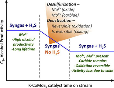
"Deactivation and stability of K-CoMoSx mixed alcohol synthesis catalysts," Journal of Catalysis (2014)
View all NREL Publications for Jesse Hensley.
Please contact me with research questions, ideas for collaborations, and questions about the Heterogeneous Catalysis for Thermochemical Conversion Program. For information on jobs, please see NREL's Director's Postdoctoral Fellowship program or on NREL Careers (search center 5100).
Share