About the Carbon Dioxide Utilization Data and Analysis
To guide research on an electron-driven carbon dioxide (CO2) reduction route, NREL performed a techno-economic analysis on select technologies and products based on a set of economic scenarios and assumptions.
These scenarios and assumptions are described below, showing the research and analysis inspired by a National Academies of Sciences, Engineering, and Medicine study. According to the study, CO2 utilization presents an opportunity to generate valuable products such as fuels, chemicals, plastics, and materials from “waste” carbon resources. Due to decreasing costs of generating renewable electricity from solar and wind, one potential route for CO2 utilization is electron-driven reduction to form versatile chemical intermediates. For more information, read Gaseous Carbon Waste Streams Utilization: Status and Research Needs, National Academies Press (2019).
Conversion Technology and Product Selection
The first stage of the economic analysis involved identification of reductive CO2 utilization pathways and products with the highest relative technical maturity as determined through literature review and subject matter expert interviews. Based on published reports, we populated a database of the top conversion technologies and the associated demonstrated products. Although many of the identified products can also serve as intermediates (e.g., carbon monoxide) for further downstream conversion to additional products, this analysis considered only single-step conversion processes.
Economic Scenarios
We recognize that many reductive CO2 utilization pathways are still in their infancy, and technology-specific parameters (e.g., operating voltage, product selectivity, and CO2 single-pass conversion) and market parameters (e.g., CO2 and electricity price) are expected to improve over time. Therefore, we considered three separate economic scenarios in the study:
- Current scenario representing the state of technology (SOT) technical parameters and $40/tonne CO2 and $0.068/kilowatt-hour (kWh) electricity
- Future scenario based on more aggressive technical parameters derived from subject matter expert interviews, comparison with similar but more mature systems, and engineering judgment with $20/tonne CO2 and $0.03/kWh electricity
- Theoretical scenario with technical parameters based on thermodynamic limitations and/or best-case assumptions and $0/tonne CO2 and $0.02/kWh electricity.
Note: Given that within a specific pathway-product combination the technical parameters and system design can vary between studies and are often conducted under different operating conditions, we acknowledge the definition of SOT can be subjective. This analysis defines the SOT from the perspective of the most commercially relevant design, giving preference to those with the longest time on stream data.
Economic Assumptions
Modeled reductive CO2 utilization processing steps include the core CO2 conversion step, recycle of unconverted feedstocks, and product purification stages. For each pathway, the materials and energy required to convert a fixed CO2 stream are quantified and used to estimate capital and operating expenses with raw material unit prices from open literature, the U.S. Energy Information Administration, and other commercial databases. The modeled system boundary does not include activities and processes common to all pathways such as electricity generation or the production and capture of waste CO2, which are instead captured as constant operating expenses.
The scale basis for the modeled conversion pathways is a 200-million-gallon-per-year (MGY) bioethanol plant as it represents an appealing entry point with high purity and low-cost CO2. The mass flowrate of emitted CO2 (MCO2 ), kg per hour) during ethanol fermentation is defined by ethanol production (Eg,f , 200MGY), CO2 emissions factor (θE.f , 6.6lb CO2 per gal ethanol) and operating hours per year (Ot , 7,884 hours per year) resulting in a value of 75,931 kg CO2/hr:
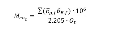
The CO2 mass flowrate from a 200 MGY bioethanol plant is also equivalent to the amount of CO2 emitted from a 100-megawatt (MW) power plant with an emission rate of 820 kg CO2/MWh and ~90% CO2 capture efficiency, which is 1 order of magnitude smaller than a typical 1,000-MW coal-fired power plant
A direct-air capture plant with airflow of ~100 million cubic meters (MCM) per hour at CO2 concentration of 415ppm, which is about half of the largest 1 megatonne (Mt) CO2/year direct air capture plant in development in the United States.
Variable operating costs are based on material and energy balance calculations under current, future, and theoretical scenarios. We assume a CO2 price of $40, $20, and $0/tonne for current, future, and theoretical scenarios, respectively.
We selected $40/tonne CO2 as a middle ground of reported cost of CO2 avoided among different carbon capture and storage (CCS) technologies; $20/tonne CO2 reflects high-purity CO2 with minimal clean-up; and $0/tonne CO2 is modeled to reflect a best-case scenario in the absence of policy credits. Electricity is priced at $0.068, $0.030, and $0.020/kWh for the current, future, and theoretical scenarios.
For the current scenario, $0.068/kWh is based on the 2017 average industrial electric rate in the United States, where $0.030 and $0.020/kWh are selected as reasonable long-term estimates for average deliverable electric rates. All hydrogen (H2) needed is assumed to be produced via water electrolysis.
NREL’s H2A: Hydrogen Production Cash Flow Analysis Model (version 3.2018) for polymer electrolyte membrane electrolysis was used to calculate the electrolytic H2 price. Applying the aforementioned electricity costs under current, future, and theoretical scenarios in the U.S. Department of Energy (DOE) H2A model, estimated production costs for electrolytic H2 are $3.91, $1.80, and $1.20/kg for the three respective scenarios.
All costs are inflation-adjusted to 2016 U.S. dollars (2016$) using the Plant Cost Index from Chemical Engineering Magazine, the Industrial Inorganic Chemical Index from SRI Consulting, and the labor indices provided by the U.S. Department of Labor Bureau of Labor Statistics.
For all five conversion pathways, annual maintenance costs are estimated at 2.5% of the total installed equipment costs, and annual fixed operating costs (i.e., salaries, property insurance, and tax) are modeled at 3% of the total installed cost (TIC). Low-temperature CO2 electrolyzers are assumed to be replaced on 7/10 year intervals at 15%/12% of total installed electrolyzer costs for current and future scenarios respectively based on previous water electrolyzer assumptions in the H2A: Hydrogen Analysis Production Model. High temperature solid oxide CO2 electrolyzers are assumed to be replaced on 4/7 year intervals at 7.5%/4% of total installed electrolyzer costs. In the theoretical scenario, it was assumed that no electrolyzer replacement was required in either case.
Electrolyzer capital costs were based on the established polymer electrolyte membrane (PEM) water electrolyzer systems published by the U.S. Department of Energy H2A program. However, whereas PEM water electrolyzers typically use platinum on the cathode, CO2 electrolyzers more often utilize cheaper metals such as copper, tin, and silver depending on the desired product. Installed electrolyzer capital costs were adjusted accordingly to account for these savings yielding installed PEM electrolyzer costs on a per square-meter (m2) basis of $18,000, $13,000, and $6,000/m2 for current, future, and theoretical scenarios. In the microbial electrosynthesis pathway, alkaline water electrolyzers are selected as the most similar configuration based on reported lower current density and aqueous environments due to constraints dictated by microorganisms. Using comparable H2A models, the installed alkaline electrolyzer costs on a per m2 basis are estimated at $1,400, $1,100, and $800/m2 for current, future and theoretical scenarios. CO2 electrolyzers in high-temperature electrolysis pathway are modeled based on the solid oxide electrochemical cell (SOEC). The calculated installed SOEC costs on a per m2 basis are $8,000, $6,000, and $4,000/m2 for the three scenarios.
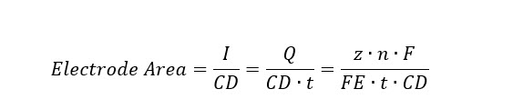
The total electrode area needed for each pathway-product electrolysis combination is then defined by the total current needed to reduce the incoming CO2 and current density (CD) under the three respective scenarios, where I is the current, z is the number of required electrons to produce one mole of product, n is the number of moles of the given product, FE is faradaic efficiency, F is Faraday's constant, t is the operating time, and Q is the total charge in Coulombs per time:
The reactor costs in biochemical (BC) and thermochemical (TC) pathways and product separation equipment costs are primarily based on industry quotes found in published NREL design reports. The key assumptions for bio- and thermo-reactor cost estimations are summarized, along with the general equipment cost assumptions for product separation processes under Capital Costs below.
With capital and operating cost data, a discounted cash flow rate-of-return analysis is generated using published engineering methods. Major financial assumptions include 40% equity financing and 3 years of construction plus 6 months for start-up.
| Economic parameters | Assumed basis |
|---|---|
| Basis year for analysis | 2016 |
| Debt/equity for plant financing | 60%/40% |
| Interest rate and term for debt financing | 8%/10 years |
| Internal rate of return for equity financing | 10% |
| Total income tax rate | 21% |
| Plant life | 20 years |
| Construction period | 3 year |
| Fixed capital expenditure schedule | 32% in year 1 |
| 60% in year 2 | |
| 8% in year 3 | |
| Start-up time | 0.5 year |
| Revenues during start-up | 50% |
| Variable costs during start-up | 75% |
| Fixed costs during start-up | 100% |
| Site development cost | 9% of ISBL, total installed cost |
| Warehouse | 1.5% of ISBL |
| Working capital | 5% of fixed capital investment |
| Indirect costs | % of total direct costs |
| Prorated expenses | 10 |
| Home office and construction fees | 20 |
| Field expenses | 10 |
| Project contingency | 10 |
| Other costs (start-up and permitting) | 10 |
| Fixed operating cost | Assumed Basis |
| Plant operators' salaries | 5.24 Operators / Shift |
| Maintenance salaries | 1% of fixed capital investment |
| Supervision and administration | 40% of operators and maintenance labor |
| Fringe benefits | 30% of total labor |
| Supplies | 1.75% of fixed capital investment |
| Insurance and local tax | 0.8% of fixed capital investment |
| ISBL=inside battery limits (of the plant) | |
The plant’s life is assumed to be 20 years. The working capital is assumed 5% of the fixed-cost investment, and income tax is 21%. For each pathway-product combination, the calculated minimum selling price (MSP) is the minimum price at which the product must sell to generate a net present value of zero for a 10% internal rate of return. It should be emphasized that although MSP is calculated as a single point value, uncertainty exists around the conceptual cost estimates. Based on availability of data, the technology readiness level of these technologies, and our analysis approach, our analysis and data reported herein are analogous to a “Class 4” study of feasibility as defined by the Association for the Advancement of Cost Engineering International Recommended Practice No. 18R-97. As such, the implied accuracy of the estimates is likely similar to the expressed class 4 range of -30% to +50%.
From the U.S. Department of Energy H2A analysis for central electrolysis, the reported capital costs for polymer electrolyte membrane (PEM), solid oxide electrochemical cell (SOEC), and alkaline water electrolyzers are used to estimate the CO2 electrolyzer capital costs for low-temperature electrolysis, high-temperature electrolysis, and microbial electrosynthesis pathways, respectively. The equation below is used to calculate CO2 electrolyzer capital costs on the basis of $/m2.
CO2 electrolyzer installed capital cost ($/m2) = uninstalled capital cost ($/kW) × Cell voltage (V) × Current Density (mA/cm2) × (1,000mA/A) × (1kW/1,000W) × (10,000cm2/m2) × installation factor
Low-Temperature and High-Temperature Electrolysis, and Microbial Electrosynthesis CO2 Electrolyzer Cost Assumptions
| Parameter | Uninstalled Capital Cost ($2016/kW) | Cell Voltage (V) | Current Density (mA/cm2) | Installation Factor | Source and/or Justification |
|---|---|---|---|---|---|
| Current | 460 | 1.9 | 2,000 | 1.12 | Source: H2A Production Model. Pt group metal is assumed 16% of uninstalled capital with anode/cathode loading ratio 7/4. |
| Future | 233 | 1.8 | 3,000 | 1.1 | Source: H2A Production Model. Pt group metal is assumed 13% of uninstalled capital with anode/cathode loading ratio 7/4. |
| Theoretical | 100 | 1.8 | 3,000 | 1.1 | Source: The Technical and Economic Potential of the H2@Scale Hydrogen Concept within the United States, NREL Technical Report (2020). Pt group metal is assumed 13% of uninstalled capital with anode/cathode loading ratio 7/4. |
| Parameter | Uninstalled Capital Cost ($2016/kW) | Cell Voltage (V) | Current Density (mA/cm2) | Installation Factor | Source and/or Justification |
|---|---|---|---|---|---|
| Current | 523 | 1.285 | 1,000 | 1.12 | Source: H2A Production Model |
| Future | 357 | 1.285 | 1,200 | 1.1 | Source: H2A Production Model |
| Theoretical | 150 | 1.285 | 2,000 | 1.1 | Source: H2A Production Model |
| Parameter | Uninstalled Capital Cost ($2016/kW) | Cell Voltage (V) | Current Density (mA/cm2) | Installation Factor | Source and/or Justification |
|---|---|---|---|---|---|
| Current | 378 | 1.75 | 175 | 1.2 | Source: H2A Production Model |
| Future | 295 | 1.65 | 200 | 1.1 | Source: H2A Production Model |
| Theoretical | 197 | 1.65 | 200 | 1.1 | Source: H2A Production Model |
| Parameter | Assumption | Year of Quote | Installation Factor | Source and/or Justification |
|---|---|---|---|---|
| Capital Cost (CAPEX) | ||||
| Bioreactor | [X/ (5.00E +5)] ^ 1.0*($782,600) | 2013 | 1.6 | Source: Process Design and Economics for Biochemical Conversion of Lignocellulosic Biomass to Ethanol, NREL Technical Report (2011) (x in unit of liter per hour) |
| Thermo-reactor | [X/ (12.5)] ^ 0.6*($872,300) | 2011 | 2.6 | Source: Process Design and Economics for Conversion of Lignocellulosic Biomass to Ethanol, NREL Technical Report (2011) (x in unit of mmscf per hour) |
Separation Process Cost Assumptions
| Parameter | Assumption | Year of Quote | Installation Factor | Source and/or Justification |
|---|---|---|---|---|
| CO2 Separation Cost ($/Metric Ton CO2 separated) | [271.3(X)]^-0.245 | 2016 | 1.0 | From IHS potassium carbonate CO2 separation system based on the total recycled CO2 amount. (x in unit of million lb per year) |
| Pressure Swing Adsorption (PSA) | [X/ (4.40 E +6)] ^ 0.65*($10,800,000) | 2010 | 1.0 | Source: A Comparative Technoeconomic Analysis of Pathways for Commercial Electrochemical CO2 Reduction to Liquid Products, Energy & Environmental Science (2018) (x in unit of mol per hour) |
| Liquid/Gas Flash Tank | [X/ (2.64E +5)] ^ 0.70*($511,000) | 2009 | 2.0 | Source: Process Design and Economics for Biochemical Conversion of Lignocellulosic Biomass to Ethanol, NREL Technical Report (2011) (x in unit of kg per hour) |
| Ethanol Distillation | [X/ (2.27E +4)] ^ 0.60*($6,008,000) | 2009 | 2.1 | Source: Process Design and Economics for Biochemical Conversion of Lignocellulosic Biomass to Ethanol, NREL Technical Report (2011) (x in unit of kg per hour) |
| Methanol Distillation | [X/ (2.27E +4)] ^ 0.60*($3,407,000) | 2009 | 2.1 | Source: Process Design and Economics for Conversion of Lignocellulosic Biomass to Ethanol, NREL Technical Report (2011) (x in unit of kg per hour) |
| Formic Acid Reactive Distillation | [X/ (1,500)] ^ 0.60*($834,000) | 2014 | 1.7 | Sources: Towards Sustainable Fuels and Chemicals Through the Electrochemical Reduction of CO2: Lessons from Water Electrolysis, Green Chemistry (2015); and Formic Acid Synthesis Using CO2 as Raw Material: Techno-Economic and Environmental Evaluation and Market Potential, International Journal of Hydrogen Energy (2016) (x in unit of kg per hour) |
| Base/Acid Mixer Tank Agitator | [X/ (1.40E+5)] ^ 0.60*($9,000) | 2007 | 3.0 | Source: Process Design and Economics for Biochemical Conversion of Lignocellulosic Biomass to Ethanol, NREL Technical Report (2011) (x in unit of kg per hour) |
| Base/Acid Mixer Tank | [X/ (1.40E+5)] ^ 0.60*($131,000) | 2007 | 3.0 | Source: Process Design and Economics for Biochemical Conversion of Lignocellulosic Biomass to Ethanol, NREL Technical Report (2011) (x in unit of kg per hour) |
| Liquid/Solid Separator | [X/ (3.20E+4)] ^ 0.80*($293,000) | 2009 | 3.0 | Source: Process Design and Economics for Biochemical Conversion of Lignocellulosic Biomass to Ethanol, NREL Technical Report (2011) (x in unit of kg per hour) |
| Acetate Membrane Separator | [X/ (3.62E+5)] ^ 0.70*($8,000,000) | 2010 | 2.0 | Estimated in Aspen Capital Cost Estimator. (x in unit of kg per hour) |
| PHB Separator | [X/ (1.60E+4)] ^ 0.80*($27,500,000) | 2011 | 1.0 | Estimated in Aspen Capital Cost Estimator. (x in unit of kg per hour) |
| Parameter | Assumption | Year of Quote | Installation Factor | Source and/or Justification |
|---|---|---|---|---|
| CO2 Recycle Stream Compressor Power (kWh) |
Calculated |
The CO2 compressor power is modeled in Aspen Plus under different scenarios based on the total recycled CO2 amount. | ||
| Pressure Swing Adsorption (PSA) Power (kWh) |
0.25 kWh/m3 gas in |
Source: General Techno-Economic Analysis of CO2 Electrolysis Systems, Industrial & Engineering Chemistry Research (2018) | ||
| Distillation Reboiler Duty (Btu) |
6,750 Btu/kg product produced |
Source: Process Design and Economics for Conversion of Lignocellulosic Biomass to Ethanol, NREL Technical Report (2011) | ||
| Amine for Formic Acid Reactive Distillation (kg) |
5.8g amine/g formic acid produced |
Source: Formic Acid Synthesis Using CO2 as Raw Material: Techno-Economic and Environmental Evaluation and Market Potential, International Journal of Hydrogen Energy (2016) | ||
| Lime for Oxalic Acid precipitation |
0.6 g lime/g oxalic acid produced |
Based on reaction stoichiometry | ||
| Sulfuric Acid for Oxalic Acid Separation |
1.1 g sulfuric acid/g oxalic acid produced |
Based on reaction stoichiometry | ||
Listed below are the major process assumptions for the five conversion pathways and their products under current, future, and theoretical scenarios.
| Product | Current Scenario | Future Scenario | Theoretical Scenario | |||||||||
|---|---|---|---|---|---|---|---|---|---|---|---|---|
|
Current Density (mA/cm2) |
Cell Voltage (V) |
Faradaic Efficiency (%) | Single-Pass CO2 Conversion (%) |
Current Density (mA/cm2) |
Cell Voltage (V) | Faradaic Efficiency (%) | Single-Pass CO2 Conversion (%) |
Current Density (mA/cm2) |
Cell Voltage (V) |
Faradaic Efficiency (%) | Single-Pass CO2 Conversion (%) | |
| Carbon monoxide | 200 | 3.00 | 98 | 1.93 | 1.33 | |||||||
| Formic acid | 140 | 3.50 | 94 | 2.08 | 1.48 | |||||||
| Oxalic acid | 75 | 6.50 | 50 | 2.30 | 1.70 | |||||||
| Methane | 225 | 2.94 | 48 | 1.66 | 1.06 | |||||||
| Methanol | 41.5 | 2.67 | 77.6 | 20 | 1,500 | 1.80 | 95 | 90 | 2,000 | 1.20 | 100 | 100 |
| Ethylene | 1,550 | 3.23 | 60 | 1.74 | 1.14 | |||||||
| Ethanol | 300 | 2.21 | 52 | 1.82 | 1.22 | |||||||
| Product | Current Scenario | Future Scenario | Theoretical Scenario | |||||||||
|---|---|---|---|---|---|---|---|---|---|---|---|---|
|
Current Density (mA/cm2) |
Cell Voltage (V) |
Faradaic Efficiency (%) | Single-Pass CO2 Conversion (%) |
Current Density (mA/cm2) |
Cell Voltage (V) |
Faradaic Efficiency (%) | Single-Pass CO2 Conversion (%) |
Current Density (mA/cm2) |
Cell Voltage (V) |
Faradaic Efficiency (%) | Single-Pass CO2 Conversion (%) | |
| Carbon monoxide | 772 | 1.41 | 99.5 | 65 | 2,500 | 1.30 | 95 | 90 | 3,000 | 0.96 | 100 | 100 |
| Methane | 1,800 | 1.45 | 12 | 11.1 | 1.25 | 1.05 | ||||||
| CO2 electrolyzer cost |
$8,000/m2 |
$6,000/m2 |
$4,000/m2 |
|||||||||
| Product | Current Scenario | Future Scenario | Theoretical Scenario | |||||||||
|---|---|---|---|---|---|---|---|---|---|---|---|---|
|
Current Density (mA/cm2) |
Cell Voltage (V) |
Faradaic Efficiency (%) | Single-Pass CO2 Conversion (%) |
Current Density (mA/cm2) |
Cell Voltage (V) |
Faradaic Efficiency (%) | Single-Pass CO2 Conversion (%) |
Current Density (mA/cm2) |
Cell Voltage (V) | Faradaic Efficiency (%) | Single-Pass CO2 Conversion (%) | |
| Formic acid | 6.8 | 2.20 | 5 |
20 |
100
|
2.08 |
95 |
90 |
200 |
1.48 |
100 |
98 |
| Acetic acid | 20.0 | 2.50 | 99 | 1.71 | 1.11 | |||||||
| Methane | 1.2 | 2.50 | 70 | 1.66 | 1.06 | |||||||
| Ethanol | 1.2 | 2.10 | 10 | 1.74 | 1.14 | |||||||
| CO2 electrolyzer cost |
$1,400/m2 |
$1,100/m2 |
$800/m2 |
|||||||||
| Product | Current Scenario | Future Scenario | Theoretical Scenario | ||||||||||||
|---|---|---|---|---|---|---|---|---|---|---|---|---|---|---|---|
| H2: CO2 | Product Selectivity (%) | Productivity (g product/ Lhr) | Product Titer (g product/L) | H2: CO2 | Product Selectivity (%) | Productivity (g product/ Lhr) | Product Titer (g product/L) | H2: CO2 | Product Selectivity (%) | Productivity (g product/ Lhr) | Product Titer (g product/L | ||||
|
Acetic acid |
2 |
100 | 1.3 | 25 | 2 | 100 | 2.6 | 60 | 2 | 100 | 10 | 100 | |||
|
Methane |
4 |
100 | 1.1 | n.a. | 4 | 100 | 6.2 | n.a. | 4 | 100 | 10 | n.a. | |||
|
Ethanol |
3.8 |
95 | 8.1 | 50 | 3 | 100 | 9.2 | 60 | 3 | 100 | 10 | 60 | |||
|
Polyhydroxybutyrate |
2.5 |
100 | 1.0 | 56 | 2.25 | 100 | 2.4 | 121 | 2.25 | 100 | 10 | 200 | |||
| Product | Current Scenario | Future Scenario | Theoretical Scenario | |||||||||||
|---|---|---|---|---|---|---|---|---|---|---|---|---|---|---|
| H2: CO2 | Product Selectivity (%) | Yield | Single-Pass CO2 Conversion (%) | H2: CO2 | Product Selectivity (%) | Yield | Single-Pass CO2 Conversion (%) | H2: CO2 | Product Selectivity (%) | Yield | Single-Pass CO2 Conversion (%) | |||
|
Carbon monoxide |
1:1 | 100 | 68 | 68 | 1:1 | 100 | 68 | 68 | 1:1 | 100 | 68 | 68 | ||
|
Methanol |
3:1 | 68 | 18 | 27 | 3:1 | 90 | 24 | 27 | 3:1 | 100 | 27 | 27 | ||
|
Methane |
4:1 | 99 | 79 | 80 | 4:1 | 99 | 84 | 85 | 4:1 | 99 | 84 | 85 | ||
|
Dimethyl ether |
3:1 | 73 | 23 | 31 | 3:1 | 90 | 31 | 34 | 3:1 | 100 | 34 | 34 | ||
|
Fischer-Tropsch Liquids |
6:1 | 78 | 42 | 54 | 6:1 | 78 | 70 | 90 | 6:1 | 100 | 100 | 100 | ||
| Current Scenario | Future Scenario | Theoretical Scenario | ||||||
|---|---|---|---|---|---|---|---|---|
|
CO2 price ($/tonne) |
40 |
20 |
0 |
|||||
|
Electricity price ($/kWh) |
0.068 |
0.030 |
0.020 |
|||||
|
Electrolytic H2 price ($/kg) |
3.91 |
1.80 |
1.20 |
|||||
|
Heat price ($/MMBtu) |
3 |
3 |
3 |
|||||
Share