Advanced Power Electronics and Electric Machines Facilities
NLR's advanced power electronics and electric machines experimentation facilities feature a range of equipment and enable world-class experimental and modeling capabilities.
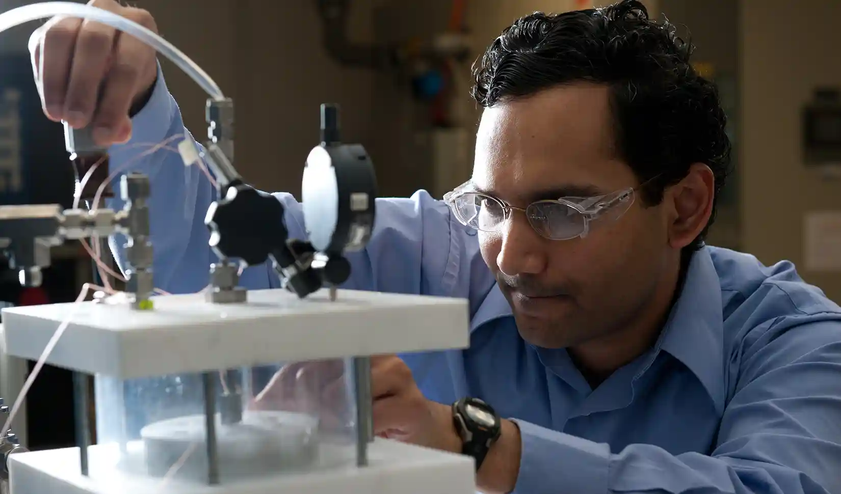
NLR researchers excel at evaluation and measurement in the areas of heat transfer, reliability characterization, package prototyping, and thermal and thermomechanical modeling.
Heat Transfer Experimentation Test Benches
NLR's power electronics researchers have several heat transfer experimentation test benches to evaluate heat transfer of electrical system components such as electric motors and inverters. These test benches allow researchers to guide the development of advanced cooling systems, such as jet impingement.
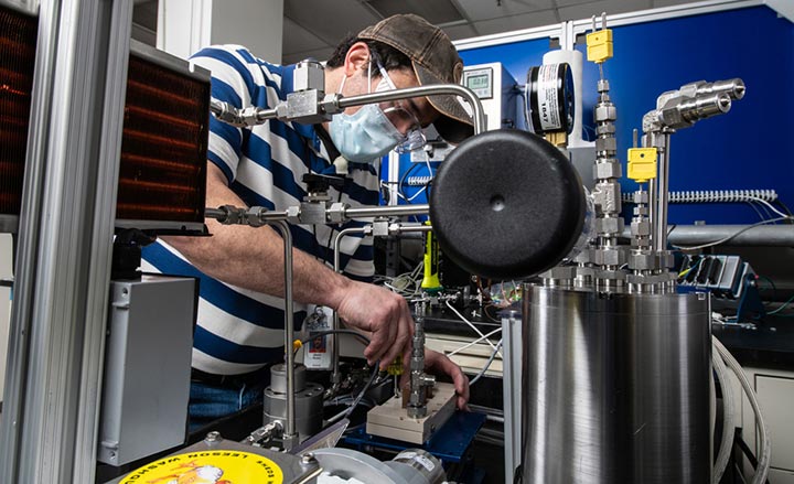
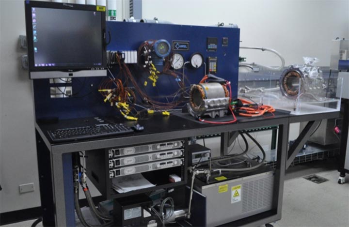
A water-ethylene glycol (50/50% by volume) flow loop is used to develop and evaluate heat exchangers, liquid jets, and spray technologies for cooling electrical system components such as electric motors and inverters. The loop delivers flow rates up to 36 liters per minute at temperatures up to 100°C. Experimental studies include the heat-transfer performance of an array of fluid flow configurations and surface enhancement techniques.
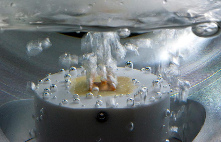
Two-phase liquid cooling includes a dedicated immersion boiling vessel, low-pressure flow loop, and high-pressure (300 psia) flow loop. All are compatible with a range of refrigerants/dielectric coolants to precisely measure and control temperature, pressure, and flow rate. The loops inform fundamental and system-level jet impingement, spray cooling, flow boiling, and pool boiling experiments to evaluate two-phase heat transfer for automotive power electronics cooling applications.
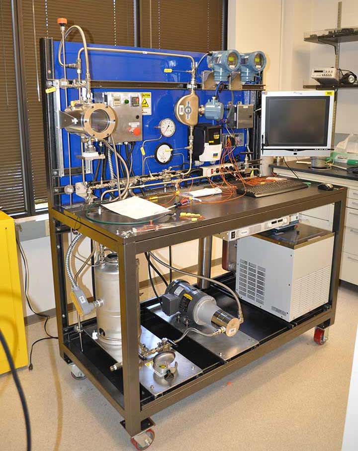
The oil-cooling flow loop characterizes the heat transfer performance of automotive automatic transmission fluid. The flow loop provides flow rates of up to 20 liters per minute and operating fluid temperatures of up to 120°C to evaluate a variety of test configurations, including channel flow, jet impingement, and larger-scale (i.e., electric motor cooling) experiments. This system is used to conduct research into the cooling of electric motors and power electronic devices.
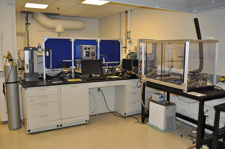
This bench measures airflow rate, pressure drop, input power, and temperature by providing air at controlled flow rates and temperatures. This bench includes an insulated test fixture for evaluating heat transfer and parasitic power losses in air-cooled heat exchangers. Additionally, researchers use hotwire anemometry and flow visualization to measure velocity fields and flow behavior. It can evaluate novel cooling technologies, including steady and synthetic air jets and heat pipes.
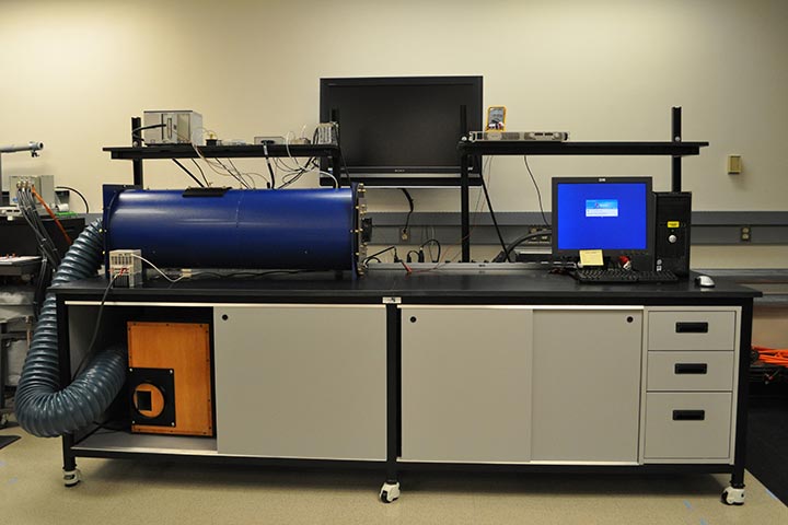
This airflow bench measures performance characteristics of fans and ducting system impedances per AMCA standard 210-99 to determine the proper selection of balance-of-system components to meet the flow specifications for heat exchanger design. The bench is capable of measuring airflow rates of 3.5 to 500 cubic feet per minute, made possible by multiple nozzles of different diameters. The bench yields highly accurate results with an average relative error in flow measurement of 1.2% and an average relative error in pressure of 0.94%.
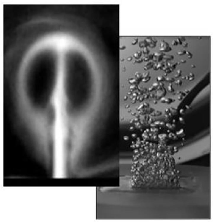
A Photron Fastcam high-speed video camera provides full resolution (1,024 by 1,024) up to 2,000 frames per second used for flow visualization of jets, flow within heat exchangers, synthetic jets, and two-phase heat transfer experiments. Higher frame rates (up to 120,000) are possible at lower resolutions. Researchers can use the camera in conjunction with a Schlieren Shadowgraph system and/or stroboscope for added visualization capability.
Thermal Characterization
Thermal characterization methods are integral to understanding the performance and reliability of power electronic components. Materials must demonstrate low thermal resistance while maintaining temperature uniformity to minimize hot spots within the device.
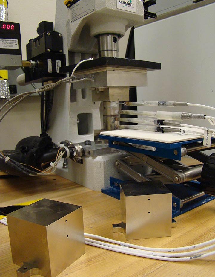
The thermal interface materials test stand provides a consistent and objective measurement of the thermal performance of greases, phase-change materials, adhesives such as thermoplastics, solders, carbon nanotubes, sintered materials, graphite, electric motor laminations, and windings. This test stand characterizes thermal resistance and thermal conductivity over a range of thicknesses and clamping forces (up to 4,400 N), at operating temperatures from 15°C to 150°C.
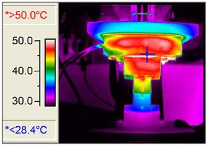
The infrared camera shows temperature distribution to identify hot spots and temperature gradients in power electronic devices. Temperature uniformity is of utmost importance to power electronic performance and reliability.
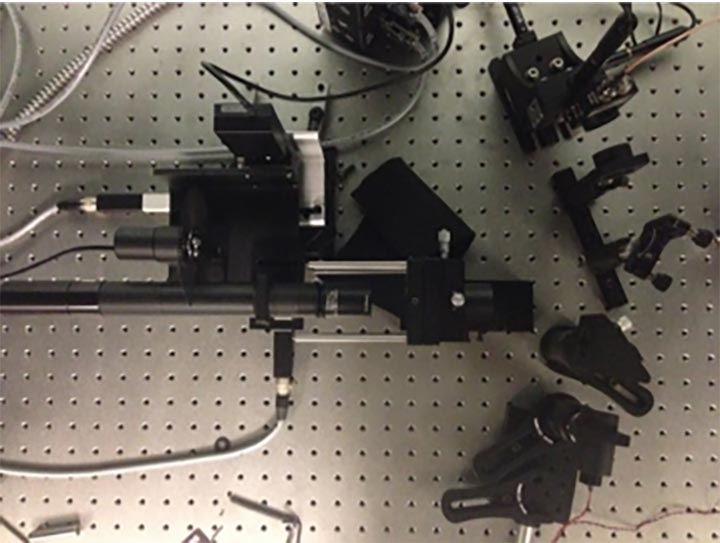
The transient thermoreflectance technique employs two localized fast lasers to determine critical thermal properties of material and interface, such as thermal conductivity and thermal resistance. A modulated pump laser is irradiated on the sample surface to induce temperature rise, and the consequent thermal wave travels through the sample, while the modulated temperature change on the other surface is detected by a probe laser.
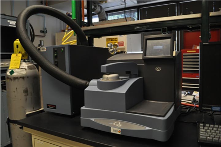
The differential scanning calorimeter measures the relative heat flow of a test sample relative to a reference standard. A number of properties—including heat capacity, glass transition point, phase transitions, polymer degradation, and oxidative stability—can be measured with this equipment.
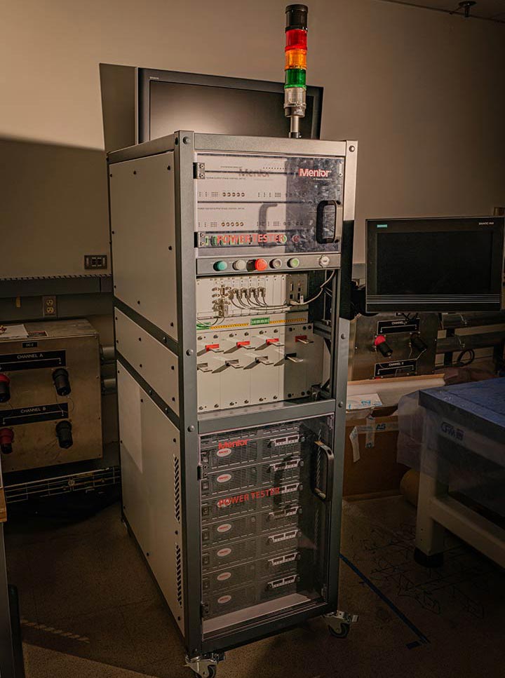
The Mentor Simcenter POWERTESTER 2400A 16C 12V transient thermal tester has four heating channels, each with a maximum output of 600 amperes (A), 12 volts for a total maximum current of 2,400 A and 16 (4 by 4) measurement channels. The POWERTESTER allows in-situ measurement of the thermal resistance of a power electronics package. Transient conduction analysis can be used to compute the resistance-capacitance network for the package and identify the resistance of select package materials. The system can power cycle devices per the AQG 324 standard and evaluate for thermal degradation via thermal resistance measurements.
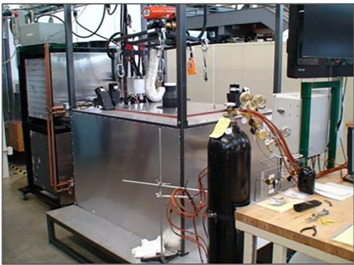
This calorimeter can measure the heat generation and efficiency of electronic components within a test cavity measuring 60 by 40 by 40 centimeters at heating rates up to 1 kilowatt under thermal isolation conditions, from -40 to 100°C. There are dual power ports for power electronics testing. It can be powered by any of the laboratory battery cyclers with a capability of 0 to 440 volts of direct current and current of 0 to 530 A.
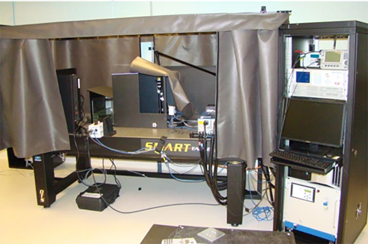
Particle image velocimetry is a nonintrusive technique to measure fluid (gas and liquid) flow fields. The information gained from this instrument can be used to optimize flow structures/paths within heat exchangers to enhance heat transfer and reduce pressure drop.
Reliability Testing
Power electronics packaging determines the electrical, thermal, and mechanical properties of a power electronics component such as an inverter. NLR researchers rely on extensive characterization through thermal, humidity, and vibration testing to better understand how stressors affect emerging technologies.
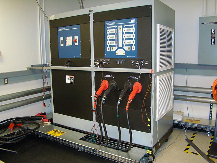
The ABC1000 is a bidirectional, programmable, computer-controlled, two-channel direct current (DC) power supply. It provides power up to 125 kilowatts, with a voltage range of 8 to 420 volts of DC and a current range of ±1000 A. In addition to evaluating power electronics, the ABC1000 can perform energy storage testing, including fast charging and fuel cell systems testing.
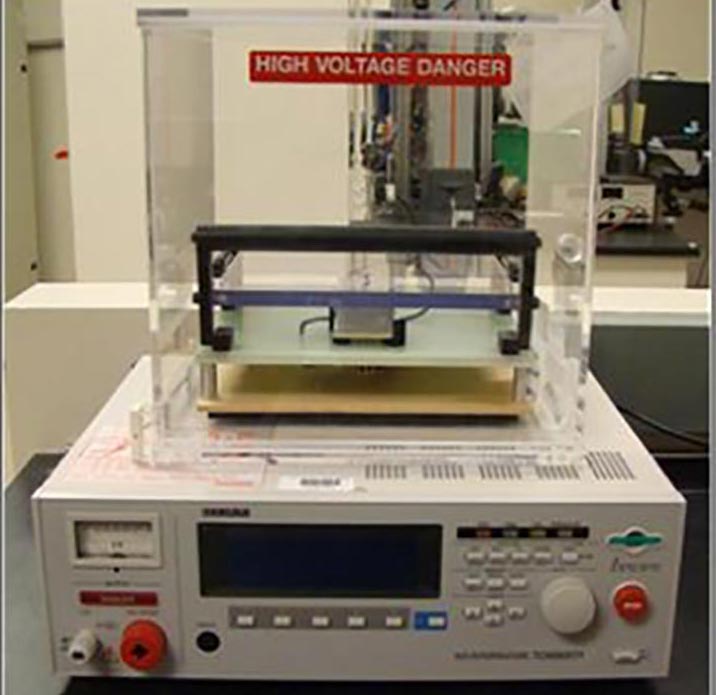
The high-potential tester measures the electrical insulating properties of sample substrates such as the aluminum nitride-based direct-bond-copper substrate. When subjected to temperature cycling or thermal shock, substrates can fail via cracking, fracture, or delamination. An increase in electrical conductivity in the tester signals a failure of the substrate.
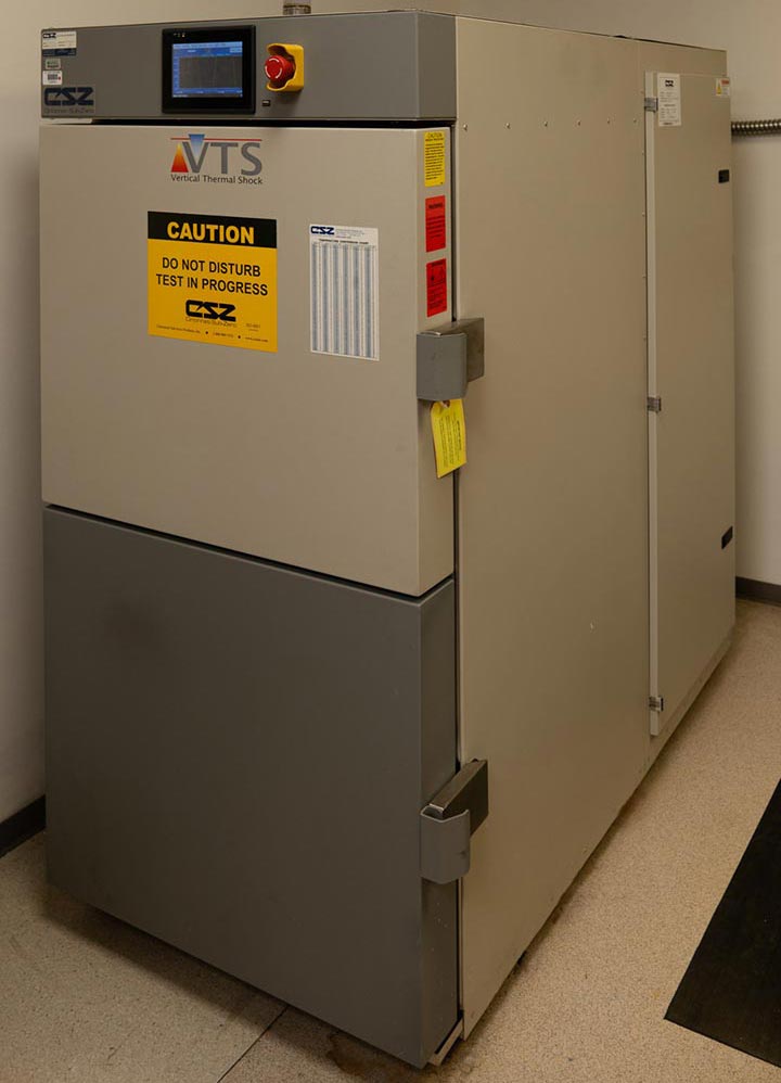
Researchers use the vertical thermal shock chamber to study thermally induced stresses in novel bonded interfaces and advanced electrical interconnects. The equipment includes a hot upper chamber and a lower cold chamber. A conveyor system moves samples between the two chambers, inducing thermal stresses under controlled conditions. The chamber has a workspace volume of 38 by 157.5 by 177.8 centimeters and is capable of operating from -75°C to 210°C.
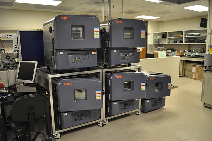
The thermal cycle testing array evaluates thermally induced stresses in novel bonded interfaces and advanced electrical interconnects at slower ramp rates (3°C to 5°C/minute) than the vertical thermal shock chamber. Multiple chambers allow for simultaneous testing of samples at various ramp rates, dwell times, or mean cyclic temperatures. The chambers have workspace volumes of 50 by 28 by 30 centimeters and are capable of operating from -70°C to 180°C.
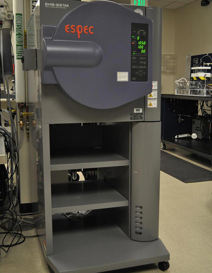
The Highly Accelerated Stress Test Chamber evaluates humidity resistance for electronic components. A pressure vessel allows for a humidity range of 75% to 100% relative humidity up to 143°C. Signal terminals allow for the measurement of samples while enclosed within the pressure vessel. The chamber has a workspace volume of 35.5 by 42.6 by 35.5 centimeters.
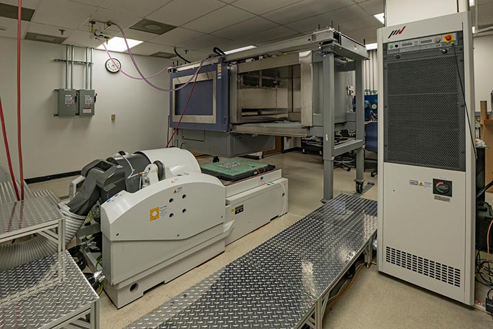
The Accelerated Drive Cycle Platform is a single-axis electrodynamic shaker with an AGREE-style environmental chamber. The chamber can operate from -40°C to 180°C and 95% relative humidity up to 85°C. This chamber can be placed directly over the electrodynamic shaker or its slip table for simultaneous temperature, humidity, and vibration control. The shaker has a rated sine force of 6,800 pounds (lb) at 92 grams (g), a random force of 6,800 lb at 65 g, or shock force of 13,500 lb of force at 153 g and a displacement up to 3 inches.
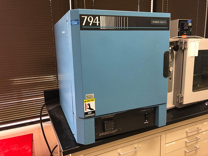
For high-temperature thermal aging of components, a ceramic oven has the capability of heating samples up to 800°C through radiative heat. Internal dimensions of the oven are 35 by 23 by 25 centimeters (length by width by height). A feed-through port is also located on the top of the oven for external monitoring equipment to directly connect to samples during tests.
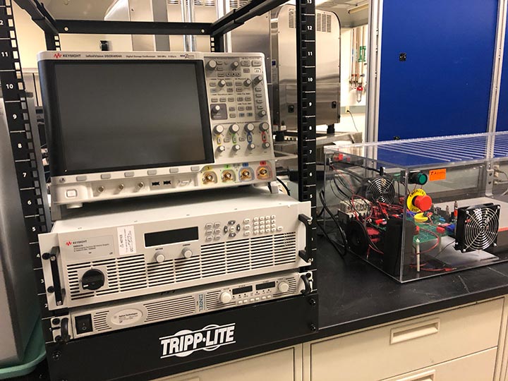
A power cycling test setup allows for cycling electrical components at up to 1,500 volts and 30 amperes at a limitation of 15,000 watts. The setup can perform switch cycling, where the total on-time is less than 150 nanoseconds. This allows researchers to open and close the conduction channel quickly to minimize self-heating effects from conduction losses and focus solely on switching events. A 500-megahertz oscilloscope with high-voltage probes can also be used for measurements.
A combination hot/cold plate allows for thermal cycling of test samples between -100°C and 250°C through a proportional integral differential controller. The work surface is 28 by 28 centimeters and features a hole pattern for securing samples.
Failure Analysis
The reliability analysis techniques used at NLR allow researchers to identify microscopic defects within material layers under different use conditions, such as pull and shear force testing.
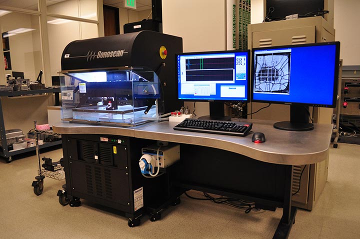
The C-Mode Scanning Acoustic Microscope uses ultrasound in the frequency range of 5 megahertz (MHz) to 230 MHz to nondestructively inspect samples for defects. The technique relies on the acoustic impedance mismatch of materials and can generate images within a sample based on scattering, refraction, and absorption of the acoustic signal within various material layers.
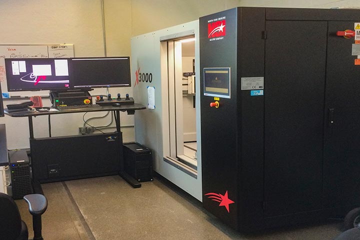
Computerized tomography (CT) scanner technology allows for nondestructive, high-precision, and high-speed inspection for applications in energy storage, power electronics, photovoltaics, hydrogen, and basic sciences. This state-of-the-art X-ray imaging system housed in the Materials Characterization Lab in the Energy Systems Integration Facility is capable of advanced 2D X-ray inspection, 2D CT slice reconstruction, CT volume reconstruction for 3D inspection, 3D internal and external surface scanning, measurement and analysis tools, 360-degree rotation, and tomography scanning.
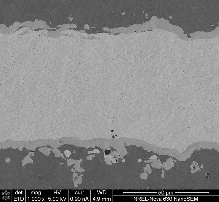
In basic scanning electron microscopy, a beam of highly energetic (0.1-50 kiloelectron volts) electrons is focused on a sample surface. This can produce several interactions, including the emission of secondary electrons, backscattered electrons, photons, and X-rays; excitation of phonons; and diffraction under specific conditions. Topography of the surface under observation can be recorded with resolution on the order of 1–2 nanometers and magnification range from 10x to 500,000x. An energy-dispersive X-ray spectroscopy detector can capture high-resolution compositional maps.
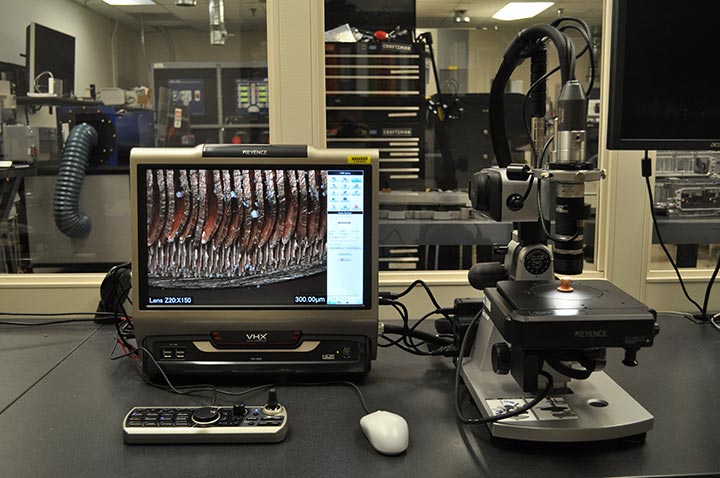
The digital microscope allows imaging of a sample's surface features at high magnifications. Lenses can enlarge an object from 20 times to 1,000 times its original size. A motorized X-Y axis stage allows researchers to digitally stitch together sample features larger than the microscope's field of view. A motorized Z-axis and stitching software provide a large depth-of-field for surface features that include varying topography.
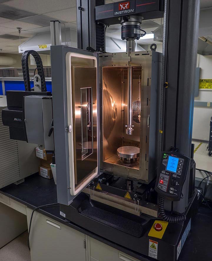
The Dual Column Tabletop Instron 5966 testing system is configured with 100 nano and 10-kilonewton load cells, capable of performing tensile, compression, shear, flexure, peel, tear, cyclic, and bend tests. This instrument has an environmental chamber with a temperature range from -100°C to 350°C for capturing temperature-dependent material properties.
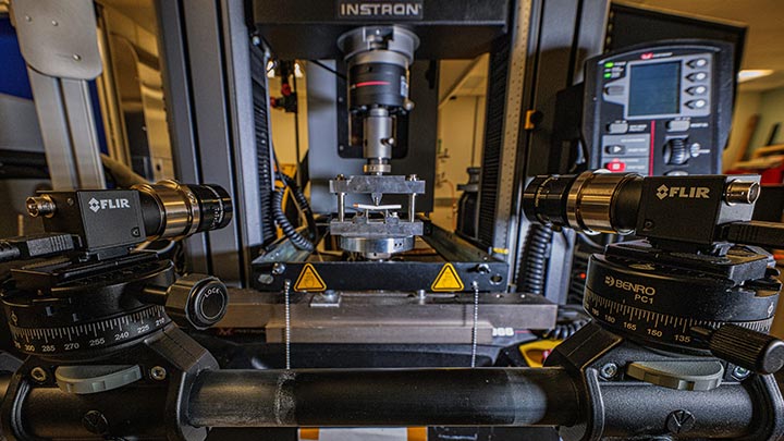
Digital image correlation is an optical-numerical measuring technique used to determine the complex shape, displacement, and deformation fields at the surface of objects under any kind of loading. A camera system monitors a speckled pattern on the surface of a part. Changes in displacement are measured, and strains can be calculated through software.
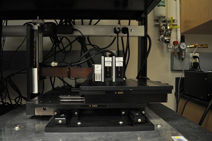
The laser profilometer provides a noncontact surface profile measurement of samples under 15 by 15 by 12 centimeters (length by width by height) in size. The laser profilometer is used to measure the curvature of samples for power electronics applications at room temperature after they have been bonded together at processing temperatures.
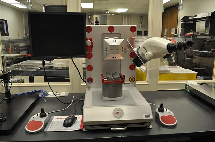
The multifunction bond tester allows for pull and shear force testing of electrical components. A revolving measurement unit uses two pull sensors and one shear sensor, each with a maximum load capacity of 100 nano. As an example, researchers can use the bond tester to evaluate the reliability of ribbon bond interconnects.
Electrical Evaluation
The Keysight B1505A Power Device Analyzer/Curve Tracer can perform various IV (current- voltage), capacitance-voltage, pulsed IV, and transient characterization of high-power devices up to 10 kilovolts of reverse voltage and up to 1,500 A of on-state current with a resolution of sub-pico A. An accessory probe-station can characterize bare semiconductor dies and patterned wafers, while a ThermoStream can control sample temperatures between -100°C to 300°C. Multifrequency alternating current measurements for inter-electrode device-capacitances can be performed for a frequency range from 1 kilohertz to 5 megahertz.
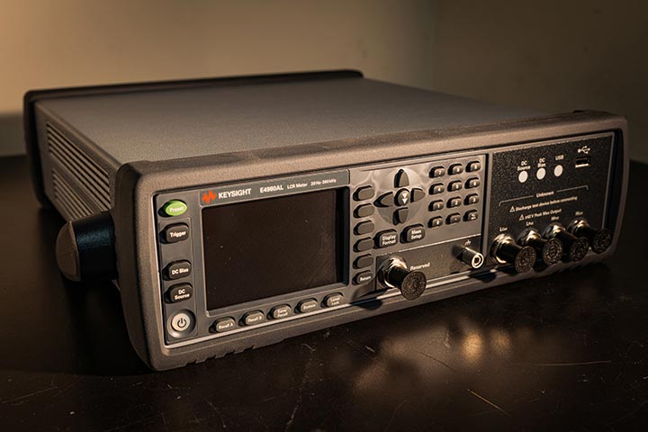
The Keysight E4980AL Precision Inductance, Capacitance, and Resistance Meter has a frequency range of 20 hertz to 300 kilohertz (kHz)/500 kHz/1 megahertz, with 4-digit resolution in any range. This meter is used to characterize capacitors and inductors used in power electronics circuits.
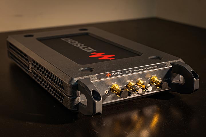
The Keysight P9370A Vector Network Analyzer has a frequency range of 300 kHz to 4.5 gigahertz and is used to characterize the electrical parasitics inside of a power electronics module.
Prototype Fabrication
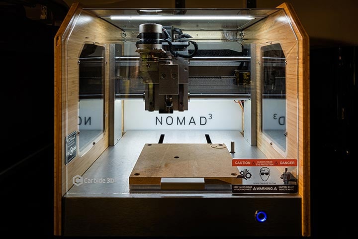
The Carbide 3D Nomad 3 is a desktop computer numerical control machine with a working area of 20 centimeters (cm) (X and Y) and working depth of 7.6 cm (Z). This machine has a 130-watt spindle motor with a maximum speed of 24,000 revolutions per minute and can be used for printed circuit board etching, rapid prototyping, and substrate etching. The Nomad can machine both 2D and 3D parts and can handle parts up to 29.5 kilograms.
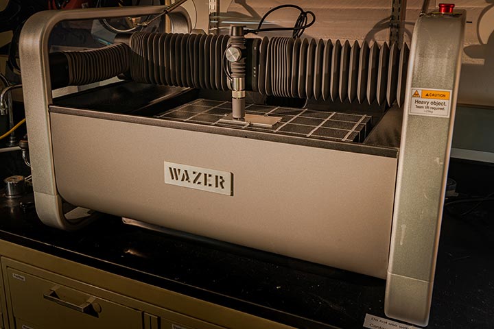
The Wazer benchtop waterjet provides a cutting area of 30.5 by 46 centimeters and can be used for precision cutting of metals, ceramics, plastics, and carbon fiber. This allows for quickly prototyping designs and destructive analysis such as cross-sectioning.
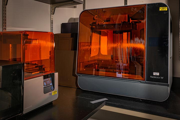
The Formlabs Form 3L is a stereolithography 3D printer with a build volume of 33.5 by 20 by 30 centimeters (width by depth by height). Stereolithography printing has the advantage of high precision, fine details, and being liquid/airtight without further post-processing. The printer has a variety of resins to choose from based on requirements of maximum loading, resistance to deformation, or stability under high temperatures.
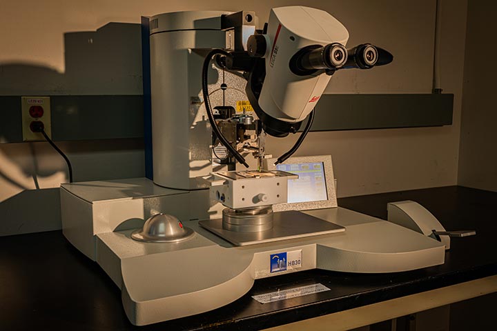
The TPT HB30 Heavy Wire Bonder is capable of bonding round wires from 100 micrometers (µm) to 500 µm and ribbons sizes up to 300 by 2000 µm with a bond force between 50 and 1,800 centinewtons. This wire bonder is a programmable semi-automatic system that provides consistency and accuracy between samples. The Z and X axes are automated to allow for repeatable loop profiles that can consist of up to 10 movement steps.
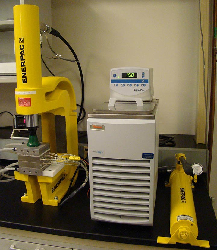
This press can apply forces up to 30 tons (~300,000 nano) when synthesizing bonded interfaces. A 1,500-watt heater is used to heat the samples to temperatures as high as 300°C. The hot press enables the synthesis of sintered interfaces based on silver and copper particles and bonded interfaces based on thermoplastics with embedded carbon fibers. It can also be used for simulating the interface between the motor laminations and water jacket.
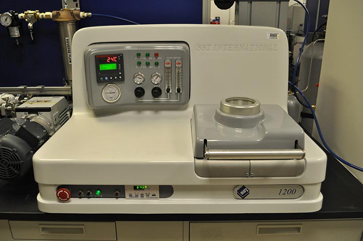
The vacuum solder reflow station enables the synthesis of flux-free and void-free solder joints. Heat is applied to a sample by a resistive graphite heating element, and the process temperature is controlled by a ramping temperature controller with preprogrammed reflow recipes. The chamber can accommodate samples up to 11.5 by 9 centimeters and be heated up to a maximum operating temperature of 450°C.
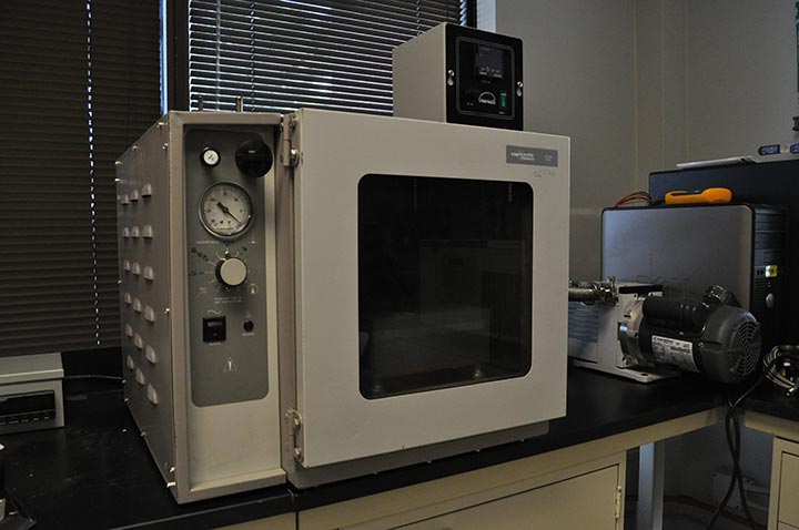
The vacuum oven with an integrated hot plate allows for the synthesis of flux-free and void-free solder joints for samples that would not fit within the vacuum solder reflow station. An external vacuum pump and argon gas are used to manually control the chamber pressure. The hot plate has a footprint of 140 by 20.5 centimeters and is capable of heating continuously up to 375°C and intermittently to 400°C.
Modeling and Simulation
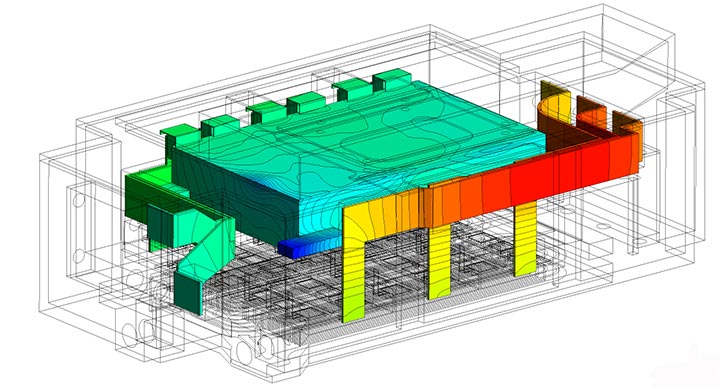
Modeling advanced power electronics and electric machines allows researchers to identify thermal bottlenecks and optimize designs.
NLR researchers use industry-standard software for modeling and simulation analysis, including ANSYS Mechanical Enterprise and ANSYS Fluent. Customized tools written in MathWorks MATLAB extend the functionality of ANSYS for design exploration and optimization. Computational hardware includes state-of-the-art workstations and NLR's flagship high-performance computing system, Kestrel, operating at 44 PetaFLOPS.
- Inverter thermal management: Inverter-scale thermal model showing component temperatures
- Electric machine thermal management: Electric machine thermal models are used to find thermal bottlenecks and optimize designs
- Packaging thermo-mechanical reliability: Viscoplastic material models are applied to substrate-attach materials to estimate the lifetime of solder and sintered silver materials
- Power device modeling: Semiconductor computer-aided modeling at micro- and nanoscales for emerging wide-bandgap and ultra-wide-bandgap devices
- Electro-magnetic design for power electronics packages: Parasitic extraction for high-frequency, low-loss wide-bandgap power modules
Contact
Share
Last Updated Dec. 6, 2025
