
EVI-InMotion: Electric Vehicle Infrastructure – In Motion Tool
NLR's Electric Vehicle Infrastructure – In Motion (EVI-InMotion) tool supports the planning, optimizing, and feasibility analysis of charging electric vehicles (EVs) while in motion using integrated charging technologies.
It applies to the full range of vehicle classes—light-, medium-, and heavy-duty—as well as various in-motion charging technologies—inductive, capacitive, and conductive. EVI-InMotion uses high-resolution travel data and detailed road network information to optimize system design parameters and evaluate performance.
Key Capabilities
EVI-InMotion optimizes dynamic charger system parameters for a given vehicle, speed trace, and road network, with a focus on charger coverage, charger power, charger location, charger length at each location, onboard battery size, and the number of power receivers on the EV.
These capabilities enable researchers to:
Evaluate the impact of dynamic chargers on EV efficiency, driving range, and charging time
Perform feasibility analyses for large-scale systems—at the city or state level—of dynamic chargers on public roadways
Explore the impact of dynamic chargers on light- and medium-duty EV intercity and intracity travel as well as heavy-duty EV local, regional, and long-haul travel
Evaluate tradeoffs between in-motion and stationary charging to inform analysis of grid interconnection impacts such as the location, distribution, size, and timing of loads.
How It Works
EVI-InMotion incorporates several models and algorithms.
Models
Vehicle Powertrain Model
Assesses EV battery power, energy, and state of charge while considering vehicle system parameters, driving behavior, and regenerative braking. Integrated with NLR’s Future Automotive Systems Technology Simulator.
Cost Model
Accounts for charger components including power converters, materials, and installation costs as well as vehicle components such as batteries and onboard electronics.
Dynamic Inductive Charger Power Model
Estimates the power an EV receives via the electrified road. One charger segment is modeled for power as a function of charger dimensions and alignment. Several segments are stacked together according to the desired electrified road length.
Algorithms
Automatic Placement Algorithm
Allocates the number and location of charger segments. Drawing on road and travel data, the algorithm designs the system based on existing road networks in the United States.
Automatic Search Algorithm
Solves a single- or multi-objective planning optimization problem, identifying the best combination of charger system parameters (e.g., power level, roadway coverage, location, length at each location, etc.) and vehicle system parameters (e.g., battery size and number of power receivers on the EV). Such optimization aims to minimize overall system costs—specifically, charger and vehicle component costs—while satisfying driving range and charging time requirements.
Applications
NLR developed two versions of EVI-InMotion—one for fixed-route applications and another for dynamic charging on public roadways.
Fixed-Route Applications
In fixed-route applications, such as with circular and on-demand shuttle services and transit buses, EVI-InMotion employs representative drive cycles to optimize system design.
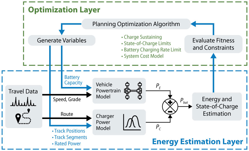
Illustration showing the EVI-InMotion process flow for studying charging systems for fixed-route applications.
Dynamic Charging on Public Roadways
EVI-InMotion is also used to inform the design of large-scale dynamic charger systems. It draws on real-world road network data as well as extensive vehicle operating data—such as drive cycles from NLR's Fleet DNA clearinghouse of commercial fleet vehicle operating data—to evaluate system performance. The system design is optimized using energy models for vehicles and chargers, along with regional performance and feasibility analyses.
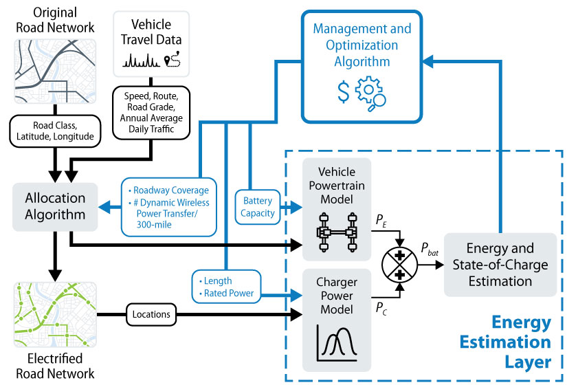
Illustration showing the EVI-InMotion process flow for studying large-scale charging systems for primary roadways in a city or state.
Publications
The following publications provide detailed information about using EVI-InMotion for planning, optimizing, and analyzing the feasibility of electric roads. View NLR's full collection of related publications.
TCO Analysis Approach and Regional Analysis of dWPT for Class 8 Tractors , NLR Presentation (2024)
In-Route Inductive Versus Stationary Conductive Charging for Shared Automated Electric Vehicles: A University Shuttle Service, Applied Energy (2021)
Contact
Contact us at [email protected] to discuss your partnership interests or to learn about our customized analyses.
Share
Last Updated Dec. 24, 2025