High-Performance Computing Data Center Cooling System Energy Efficiency
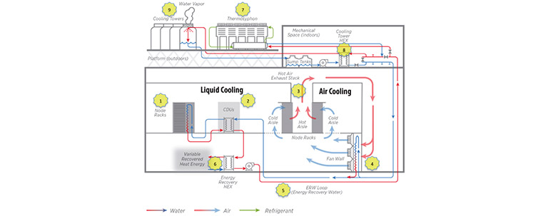
Follow this schematic to see how the Energy Systems Integration Facility's (ESIF's) High-Performance Computing Data Center (HPC Data Center) cooling system works.

Starting in the ESIF HPC Data Center (1), IT equipment, such as compute clusters and data storage systems, produces heat as a byproduct. Data center operators require 90% or more of the heat produced to be acquired via a liquid cooling approach.
Most liquid cooling approaches involve a cooling distribution unit (CDU) (2), which interfaces with the facility cooling loop and provides cooling liquid at the appropriate temperature, pressure, and chemistry for the IT equipment.
For IT equipment that is not liquid-cooled, the byproduct heat dissipates to air, where it travels through the ceiling plenum (3) and is cooled by a set of fan walls (4). The fans are analogous to a computer room air handler (CRAH) in a typical data center.
All heat energy from the data center is captured to the energy recovery water (ERW) loop (5), which is a closed-loop system. There are three heat rejection options for this IT load, which operate according to the following hierarchy:
When possible, heat energy from the energy recovery loop is transferred to the building process hot water (PHW) loop, which provides heat for the office and laboratory spaces within the building. The energy recovery heat exchanger (6) transfers heat from the ERW loop to the PHW loop.
After re-use potential is exhausted, warm ERW water flows to the fourth floor mechanical room. When temperatures permit, heat is dissipated through a thermosyphon (7), which is an advanced dry cooler that uses refrigerant in a passive cycle to dissipate heat.
Remaining heat is transferred from the ERW loop to a tower water (TW) open loop via the cooling tower heat exchanger (8). Cooling towers (9) cool the TW loop by cascading that water across fill material while drawing ambient air across the fill material. This provides a very energy-efficient way to cool water with sensible (heat dissipated to air without evaporation) and latent (heat dissipated with evaporation) heat transfer. However, this evaporative cooling process requires a continuous source of water.
Share
Last Updated April 10, 2025
