Thermal and Catalytic Process Development Unit
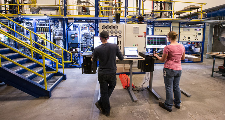
The Thermal and Catalytic Process Development Unit (TCPDU) at NREL has state-of-the-art equipment for thermochemical process development and testing, ranging from catalyst and feedstock characterizations to bench-scale reactors to pilot plants.
We welcome partners who wish to collaborate on research and development efforts or to use our equipment to test their materials and processes.
In addition to the following testing systems, we have several other lab-scale reactor systems and the ability to engineer and fabricate custom systems.
Pilot-Scale Systems
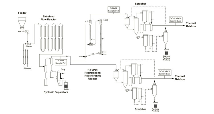
Thermal and Catalytic Process Development Unit – Pyrolysis
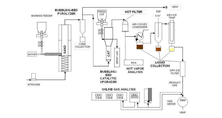
The Thermal and Catalytic Process Development Unit (TCPDU) is used to test biomass pyrolysis technologies at the pilot scale. The TCPDU can be configured for fast pyrolysis and catalytic pyrolysis. An entrained flow reactor is used to generate the pyrolysis vapors, cyclones to collect char and ash, and a spray condensation train to collect the final products. A recirculating regenerating reactor can be used to catalytically upgrade the pyrolysis vapors. Online analytical capabilities include molecular beam mass spectrometry, gas chromatography, thermal conductivity detection, and nondispersive infrared. Partners can use the TCPDU to test catalysts or bring in their own unit operations to attach to the TCPDU to test their pyrolysis technologies.
Learn more about NREL's thermochemical process integration, scale-up, and piloting research.
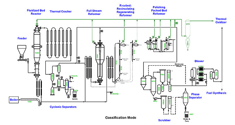
Thermal and Catalytic Process Development Unit – Gasification
The TCPDU is also used to test biomass gasification technologies at the pilot scale. In the gasification configuration, the TCPDU is comprised of a fluid bed reactor for initial volatilization of biomass, a thermal cracker to complete gasification, cyclones for char and ash collection, and a gas scrubbing system. Three different reforming reactors are available and can be used independently or in parallel: fluid bed, packed bed, and recirculating regenerating reactor. Online analytical capabilities include molecular beam mass spectrometry, gas chromatography, thermal conductivity detection, and nondispersive infrared. Partners can use the TCPDU to test catalysts or bring in their own skid to attach to the TCPDU to test syngas upgrading technologies.
Learn more about NREL's thermochemical process integration, scale-up, and piloting research.
Davison Circulating Riser
The Vapor Phase Upgrading Lab houses two reactor systems: a fluidized bed reactor for the fast pyrolysis (500°C, 20–45 psig, 1–2 seconds residence time) of biomass and a Davison circulating riser (DCR) for performing vapor phase upgrading reactions of pyrolysis vapors. The scale of operations on the pyrolyzer is nominally 2 kg/hour, with nitrogen employed for fluidization (0.5 biomass:N2). Pyrolysis vapor feed rates up to 1 kg/hour (including nitrogen) to the DCR are typically employed to provide short residence times (~1 second) in the DCR. The DCR (500°C–650°C, 20–45 psig, 1–10 seconds residence time) circulates a 2 kg charge of catalyst through a steam stripper and a regenerator (for coke removal) that allows up to 10 to 12 hours of continuous operation per day. Weight hourly space velocity between 10 (typical for pyrolysis vapors) and >100 (vacuum gas oil) enable a wide range of experimental conditions for catalyst evaluation. The lab also houses a Xytel attrition testing unit (to determine if novel catalysts are suitable for circulation in the DCR), fixed gas detection, and an overhead crane.
Learn more about NREL's thermochemical process integration, scale-up, and piloting research.
Laboratory-Scale Reactor Systems
Fuel Synthesis Catalysis Laboratory
NRELs Fuel Synthesis Catalysis Laboratory (FSCL) is a purpose-built facility designed for testing heterogeneous catalysts in their role of converting biomass intermediates to chemicals and fuels. A variety of reactor systems, customized for the challenges of bio-intermediate upgrading, can be used to test various materials and process conditions. Alternately, reactor bays are equipped to handle new designs or customer-supplied equipment. In-house developed, partner-supplied, and purchased catalysts can be tested across operating conditions that span 0–2,000 psig (pressure), 150°F–1,800°F (temperature), permanent and condensable gases, liquids, and vaporizable solids. Full process automation allows for extended operation up to thousands of hours. Product analysis is achieved through online chromatography and mass spectrometry and a multitude of offline techniques, like nuclear magnetic resonance, high-performance liquid chromatography, scanning electron microscopy with X-ray microanalysis, transmission electron microscopy, X-ray diffraction, Fourier transform infrared spectroscopy, Raman, etc.
Learn more about NREL's heterogeneous catalysis for thermochemical conversion research.
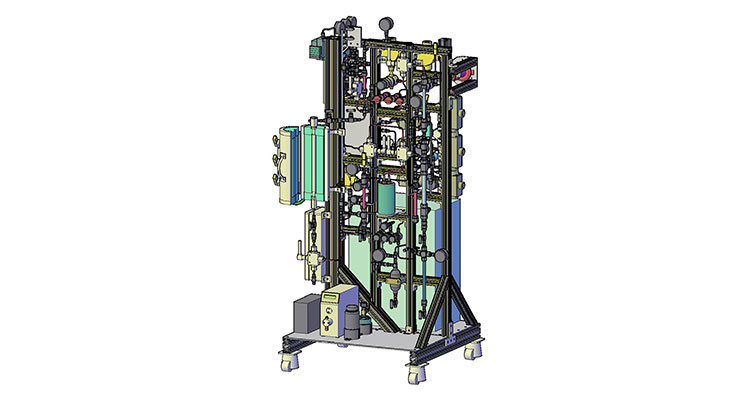
Research Gasifier
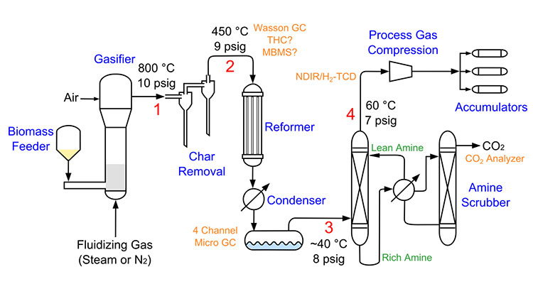
The NREL Research Gasifier (NRG) is a compact, fully automated gasification system that consists of biomass feeding, gasification, solids removal, tar and hydrocarbon reforming, liquids condensation, CO2 removal, gas compression, and syngas storage for future use. The individual sub-systems of the NRG can be manipulated for individualized research.
Learn more about NREL's thermochemical process integration, scale-up, and piloting research.
Bench-Scale Biomass Conversion System
The two-inch fluidized bed reactor system is a valuable intermediate between micro-scale experiments and larger pilot-scale experiments. In its current configuration, it receives solid biomass powder (sawdust) at rates of several hundred grams per hour and converts it to tangible quantities of liquid-fuel precursors as well as solid and gaseous co-products. These products are then thoroughly analyzed chemically and physically, as well as further upgraded by hydroprocessing so as to evaluate and compare biomass feed materials, catalysts, thermal conditions, and reactor conditions to identify promising processes for the economic production of fuels and chemicals from biomass.
Laminar Entrained Flow Reactor
The Laminar Entrained Flow Reactor (LEFR) is a modular, laboratory-scale, single-user reactor for studying catalytic fast pyrolysis (CFP). This system can be used to study a variety of reactor conditions for both in situ (in place) and ex situ (out of place) CFP.
NRELs custom-built LEFR system continuously produces char-free pyrolysis vapors and delivers them to a second, independently controlled, catalytic reactor. The secondary reactor can be configured as a four-channel fixed bed or drop tube reactor. Catalyst performance and deactivation can be studied at small scale with real biomass pyrolysis vapors. Used catalyst is removed from the vapor stream for further analysis or regeneration. Solid char, liquids, and the outlet gas yields are measured to provide a quantitative mass balance.
Analytical and Characterization Laboratories
Molecular Beam Mass Spectrometry
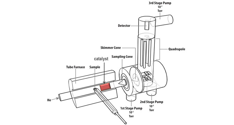
Molecular beam mass spectrometry (MBMS) is used to characterize gases and vapors that evolve from biomass thermochemical conversion and catalytic upgrading processes. NREL has six MBMS systems: two stationary systems, two field-deployable systems (customized for use in industrial environments), and two high-throughput stationary systems with autosampler pyrolysis units. The advantages of this technique include real-time, continuous monitoring; direct sampling from harsh environments, including high-temperature, wet, particulate-laden or corrosive gas streams; nearly universal detection capabilities; and a large dynamic range (106–10-2 ppmv). Applications have included:
- Analytical pyrolysis for material characterization, including early detection of chemical differences in genetically modified biomass crops
- Mechanisms and kinetics of thermochemical processes, including identifying thermal degradation pathways and modeling the deactivation of steam reforming catalysts
- Heterogeneous catalyst screening and product yield estimates
- Reaction parameter screening for engineering scale-up
- Monitoring and speciation of biomass-derived syngas and diesel engine exhaust.
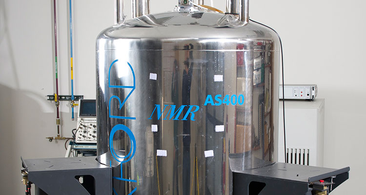
Magnetic Resonance Facility
NREL's state-of-the-art Magnetic Resonance Facility provides both liquid and solid-state analysis for a variety of biomass, photovoltaic, and materials characterization applications on three nuclear magnetic resonance (NMR) spectrometers. Our 600 MHz Bruker Avance III NMR spectrometer provides high-throughput, quantitative liquids analysis using a Bruker Sample Jet, cutting-edge analysis of semi-solid samples using a high-resolution magic angle spinning probe, a high sensitivity liquid-state Bruker CryoProbe, and solid-state analyses of biomass feedstocks, biomass-related materials, and polymers. The 400 MHz Bruker Avance III HD NanoBay NMR spectrometer allows NREL scientists to run their own liquid sample analysis using a Bruker SampleCase autosampler for routine 1H, 13C, 31P, and 19F experiments, temperatures studies from -40°C to 80°C, and has the capability of a Bruker Prodigy CryoProbe for increased sensitivity. The 200 MHz Bruker Avance III HD NMR Spectrometer is ideal for solid-state 13C NMR studies of various materials and also offers a 10 mm liquids probe for rapid 13C analysis.
Biomass Catalyst Characterization Laboratory
NRELs Biomass Catalyst Characterization Laboratory is a comprehensive materials characterization and performance testing laboratory. Material characterization capabilities span a range of physical and chemical techniques.
Contact
For contacts, see Work With Us.
Share